Learning Outcomes
When you have completed this module, you will be able to:
- Describe reference files and explain how they are used in an AutoCAD drawing.
- Apply the XREF command.
Reference Files
An external reference file is a drawing file linked to the current drawing. It acts as one object similar to a block and appears to be part of the current drawing. Usually called a reference file or a xref, it is quite different from a block. A reference file updates itself whenever the drawing it is linked to is opened. It can also be updated manually by the CAD operator. If the drawing that is attached as an xref is changed, the changes will appear when the drawing it is attached to is opened or reloaded. Since it is only linked to the drawing, it does not add a significant amount of data to the drawing’s database.
The XREF command is used to manage the reference files that are linked to the current drawing. You can attach more than one reference file at the same time. All objects in the reference file must be in Model space. Reference files can be scaled or rotated when they are attached with the XREF command or after they are attached with the SCALE and/or ROTATE commands. You can snap to the object snap modes of objects in the reference files. A reference file can be edited in the current drawing with the changes going back to the original drawing file. This is done with the REFEDIT command.
Xref Dependant Named Objects
Xref dependent named objects are the layers, linetypes, dimension styles, blocks, and text styles of the reference file. They are added to the drawing they are attached to as non-graphical object information. The names are changed so that no two names are the same. Table 35-1 shows how the non-graphical names are dealt with by AutoCAD.
This table demonstrates how AutoCAD names the xref dependent named objects for layers, linetypes, dimension styles, blocks, and text styles. In this table, the name of the attached xref file drawing is House Plan and a layer in that drawing is First Floor and a block named Coffee Table. For a reference file, the name of the non-graphical object is changed to the name ‘ drawing name|object ‘. If it is bound to the drawing, it is renamed ‘ name$n$objectname ‘. The ‘ n ‘ starts with zero and increases by one if the same name is encountered.
Binding a Reference File
A reference file can be bound to the current drawing it is attached to with the XREF command. When a reference drawing is bound to the drawing, the XREF command converts it into a block. The xref dependent named objects are renamed according to Table 35-1. A block can be exploded to convert the objects into single objects and they become part of the drawing. When a reference file is bound, it can either be bound or inserted. Inserting a reference file converts it into a block but it strips the named non-graphical objects back to their original names. See Table 35-1

Naming of Xref Dependent Named Objects
AutoCAD Command: XREF
The XREF command is used to manage reference files in the current drawing.
Shortcut: XREF or XR

WORKALONG: Using Reference Files
Step 1
Open drawing: AutoCAD 2D Lab 32-3.
Step 2
Open the Units dialogue box and set the Insertion scale to millimeters.
Step 3
Using the SAVEAS command, save and name the drawing four times to create four identical drawings with the following names:
AutoCAD 2D Workalong 35-1A
AutoCAD 2D Workalong 35-1B
AutoCAD 2D Workalong 35-1C
AutoCAD 2D Workalong 35-1D
Step 4
Close drawing: AutoCAD 2D Lab 32-3.
Step 5
Open drawing: AutoCAD 2D Workalong 35-1A. (Figure Step 5)
Step 6
Ensure that all layers are on and thawed.
Step 7
Turn layer: Lot Lines off. Enter the ZOOM Extents command. Erase all visible objects on the drawing. The drawing should appear blank.
Step 8
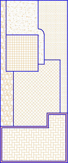
Turn layer: Lot Lines on. Your drawing should match the figure. (Figure Step 8)

Step 9
Purge all layers and blocks that can be purged from the drawing.
Step 10
Save and close the drawing.
Step 11
Open drawing: AutoCAD 2D Workalong 35-1B.
Step 12
Ensure that all layers are on and thawed.
Step 13
Turn layer: Object off. Enter the ZOOM Extents command. Erase all visible objects on the drawing. The drawing should appear blank.
Step 14
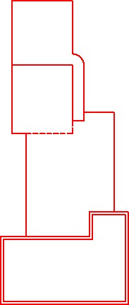
Turn layer: Object on. The drawing should match the figure. (Figure Step 14)
Step 15
Purge all layers and blocks that can be purged from the drawing.
Step 16
Save and close the drawing.
Step 17
Open drawing: AutoCAD 2D Workalong 35-1C.
Step 18
Ensure that all layers are on and thawed.
Step 19
Turn layer: Boundary off. Enter the ZOOM Extents command. Erase all visible objects on the drawing. The drawing should appear blank.
Step 20
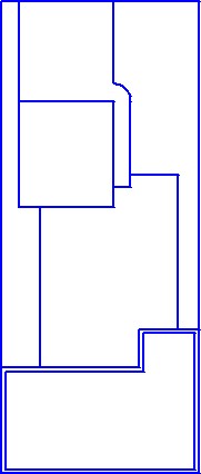
Turn layer: Boundary on. The drawing should match the figure. (Figure Step 20)
Step 21
Purge all layers and blocks that can be purged from the drawing.
Step 22
Save and close the drawing.
Step 23
Open drawing: AutoCAD 2D Workalong 35-1D.
Step 24
Ensure that all layers are on and thawed.
Step 25
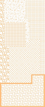
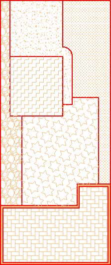
Turn layer: Lot Hatch off. Enter the ZOOM Extents command. Erase all visible objects in the drawing. The drawing should appear blank.
Step 26
Turn layer: Lot Hatch on. The drawing should match the figure. (Figure Step 26)
Step 27
Save and close the drawing.
Step 28
Start a new drawing using the template: 2D Layout Metric.
Step 29
Save and name the drawing: AutoCAD 2D Workalong 35-1.
Step 30
Open the Units dialogue box and set the Insertion scale to millimeters.
Step 31
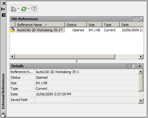
Enter the XREF command to open the External References window. (Figure Step 31)
Step 32
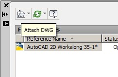
Click the Attach DWG icon. (Figure Step 32)
Step 33
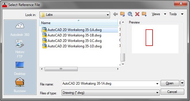
In the Select Reference File dialogue box, select the drawing: AutoCAD 2D Workalong 35-1A.dwg. (Figure Step 33)
Step 34
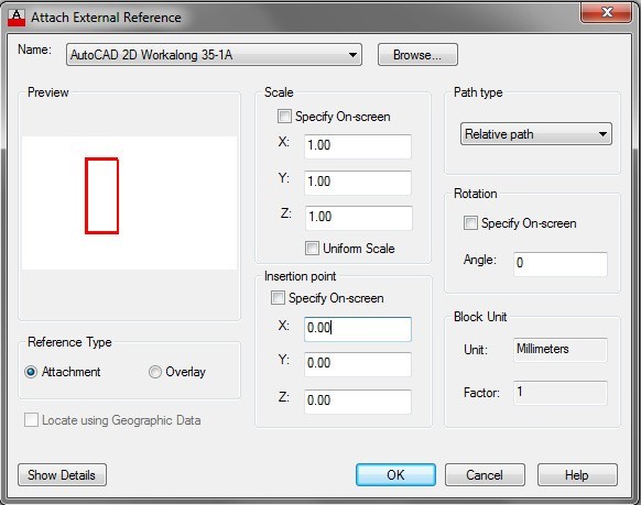
In the Attach External Reference dialogue box, set your dialogue box to match the figure. (Figure Step 34)
Step 35
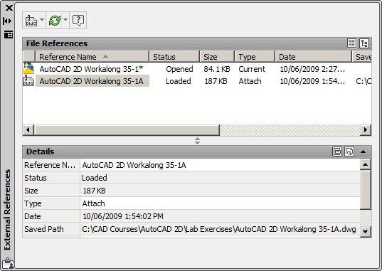
In the External References window, you should see the drawing you just attached and the drawing you currently have open. (Figure Step 35)
Step 36
Enter the ZOOM Extents command. (Figure Step 36)

Step 37
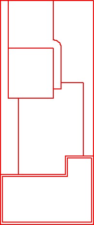
Using what you just learned, attach the drawing: AutoCAD 2D Workalong 35-1B as a reference file. (Figure Step 37)
Step 38
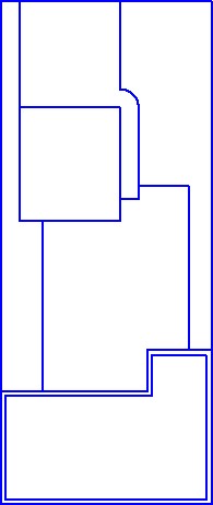
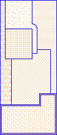
Attach the drawing: AutoCAD 2D Workalong 35-1C as a reference file. (Figure Step 38)
Step 39
Attach the drawing: AutoCAD 2D Workalong 35-1D as a reference file. (Figure Step 39)
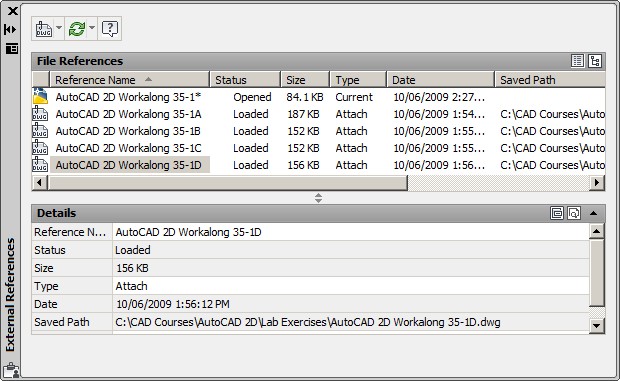
Step 40
The External Reference window should match the figure. (Figure Step 40)
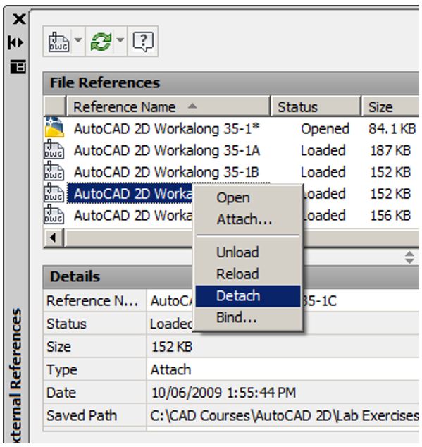
Step 41
In the External Reference window, select the drawing: AutoCAD 2D Workalong 35-1C. Right click the mouse. In the Right-click menu, click Detach. (Figure Step 41A and 41B)
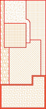
Step 42
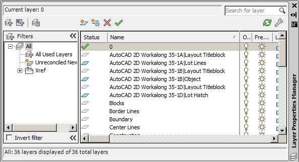
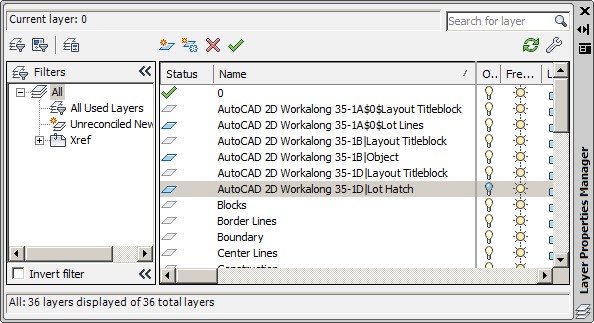
Open the Layer Properties Manager window. Take note of the layer names of the layers of the attached referenced files. (Figure Step 42)
Step 43
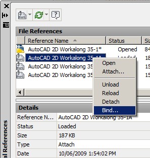
In the External Reference window, select the drawing: AutoCAD 2D Workalong 35-1A. Right click the mouse. In the Right-click menu, click Bind. (Figure Step 43)
Step 44
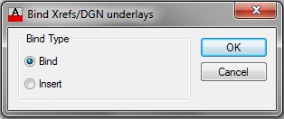
In the Bind Xrefs dialogue box, enable Bind and click OK. (Figure Step 44)
Step 45
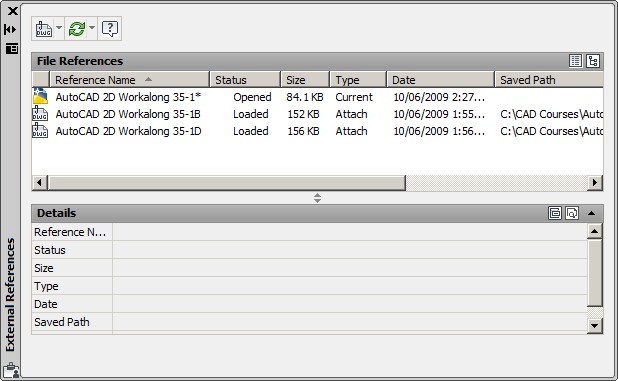
The External Reference window should match the figure. (Figure Step 45)
Step 46
Your drawing should as shown in the figure. (Figure step 46)
Step 47
In Layer Properties Manager window, turn off layer: AutoCAD 2D Workalong 35-1D|Lot Hatch. (Figure Step 47)
Step 48
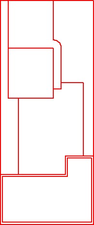
Your completed drawing should match the figure. (Figure step 48)
Step 49
Save and close the drawing.
Key Principles
Key Principles in Module 35
- An external reference file is a drawing file linked to the current drawing. It acts as one object similar to a block and appears to be part of the current drawing.
- A reference file can be bound to the drawing it is attached to with the XREF command. When a reference drawing is bound to the drawing, the XREF command converts it into a block.
- To completely remove a reference file from the current drawing, it must be detached using the XREF command.
Lab Exercise 35-1
Time allowed: 50 minutes.
| Drawing Name | Template | Units |
|---|---|---|
| AutoCAD 2D Lab 35-1 | 2D Layout English | Inches |
Step 1
On layer: Object, draw the Polygon Multi-Tool shown in the figure. (Figure Step 1A, 1B, and 1C)

Completed Drawing
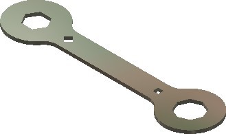
Polygon Multi-Tool
Step 2
Set the insertion units and check your drawing with the key. Turn layer: Key off and freeze layer: Construction.
Lab Exercise 35-2
Time allowed: 50 minutes.
| Drawing Name | Template | Units |
|---|---|---|
| AutoCAD 2D Lab 35-2 | 2D Layout Metric | Millimeters |
Step 1
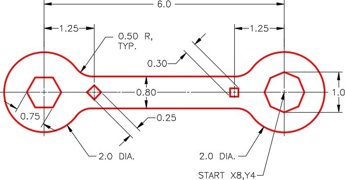
On layer: Object, draw the Double Hexagon Wrench shown in the figure. (Figure Step 1A, 1B, 1C, and 1D)
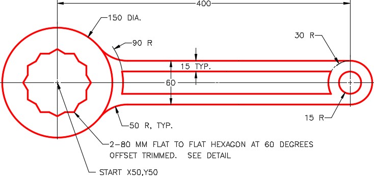
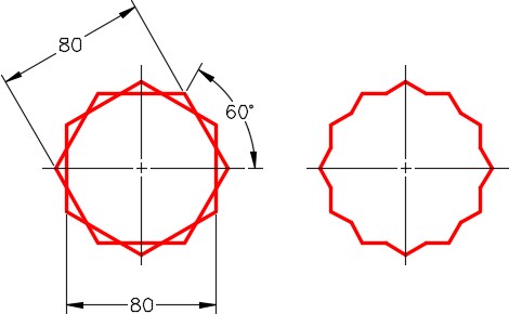
Detail

Completed Drawing
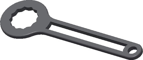
Double Hexagon Wrench
Step 2
Set the insertion units and check your drawing with the key. Turn layer: Key off and freeze layer: Construction.

