
Chapter 1: AutoCAD’s User Interface
Learning Outcomes
When you have completed this module, you will be able to:
- Describe and configure AutoCAD’s interface including the Graphic window, crosshairs, Graphic cursor, pickbox, Status bar, Model and Layout tabs, Pull-down menu, Toolbar menus, Ribbon menus, dialogue boxes, windows, using of the mouse, Command Line window, and the Text window.
- List and describe the two basic AutoCAD menus systems; Toolbars and Ribbons.
AutoCAD’s Graphic Window
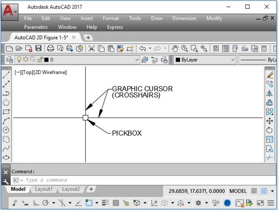
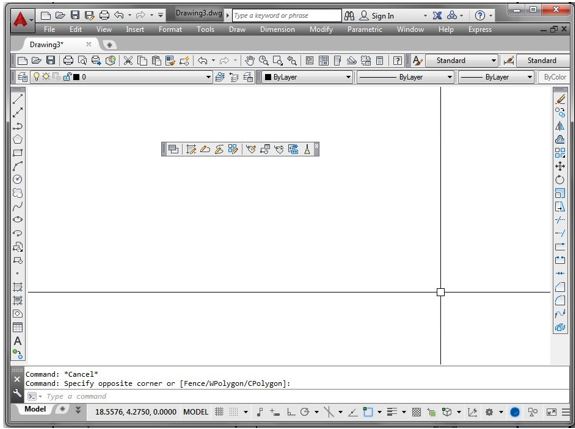
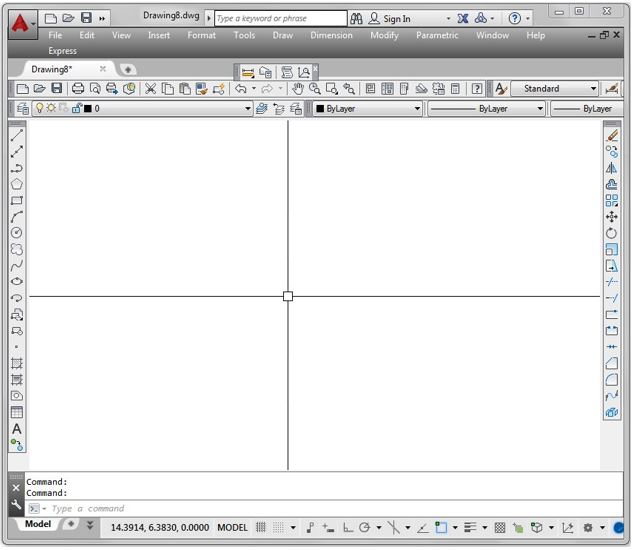
AutoCAD’s Graphic window is shown in Figure 1-1. The Graphic window is used most of the time when you are working in AutoCAD.
Crosshairs and Graphic Cursor
The crosshairs indicates your current location on the Graphic window or in 2D space. If you were drawing by hand, think of it as the point of your pencil. It is one of AutoCAD’s most important features and is used extensively when you are creating drawings. See Figure 1-1, and 1-3.
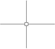
When you move the crosshairs onto a menu item, it will change its display to the Graphic cursor as shown in Figure 1-2. You use it to select menu items.

Pickbox
The pickbox is a small square located at the intersection of the crosshairs as shown in Figure 1-3. It is used to pick drawing objects.
Status Bar
The Status bar, Figure 1-4, is positioned across the bottom of the Graphic window and becomes a very important part of your day-to-day AutoCAD work.

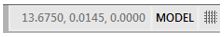
The coordinate location or the XYZ coordinates of the current location of the crosshairs is displayed near the center of the Status bar. The coordinate location display can be enabled or disabled by clicking it with the left mouse button. Toggle buttons for AutoCAD’s features are located immediately to the right of the coordinate display. Many of these features will be taught in the AutoCAD 2D book.
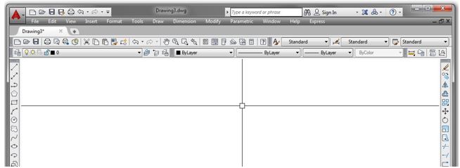
Model and Layout Tabs
The Model and Layout tabs, Figure 1-5, are used to toggle the display of Model space or one of the layouts. This will be discussed in greater detail in Module 18.

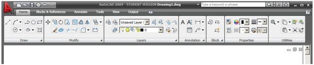
AutoCAD’s Menu Systems
AutoCAD has two different menu systems that allows you to communicate with it. The two menu systems that you can choose from are the Toolbar menus and the Ribbon menus. See Figure 1-6. You can and should add the Pull-down menu to either the Toolbar or the Ribbon menu.
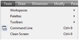
Pull-down Menus
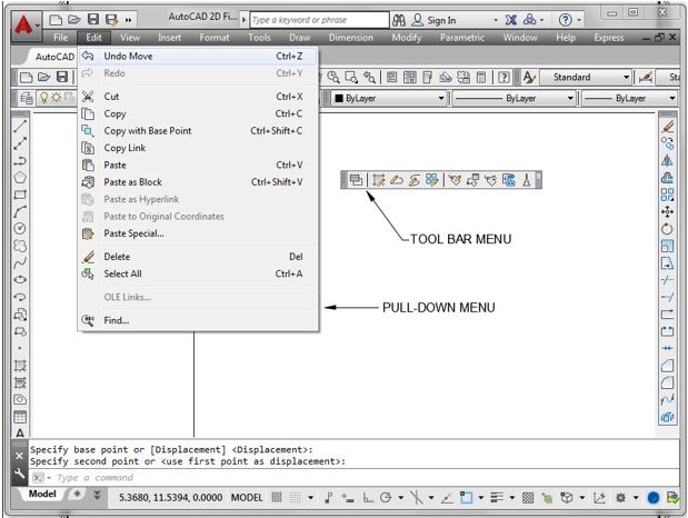
The Pull-down menus are located across the top of the Graphic window. When you click one of the items on the menu, with the left mouse button, the menu will pull down as shown in Figure 1-7 and 1-8.
A Pull-down Menu Flyout
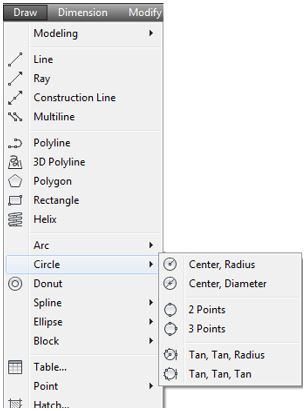
If an item on the Pull-down menu has a small solid triangle at the end, it has a Flyout menu associated with it. Place the Graphic cursor on the triangle to force the Flyout menu to display as shown in Figure 1-9.
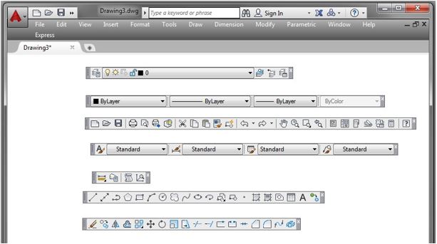
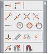
Toolbar Menus
Toolbar menus are a series of icons that are located on a collection of menu bars. See Figure 1-10. The display of each toolbar can be enabled or disabled at your discretion. If they were all displayed at the same time, they would virtually fill the Graphic window. Therefore, their display must be enabled or disabled, as required, by the current operation in the drawing.
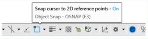
Toolbars can float inside the Graphic window or they can be docked along any one of its four sides. If the Graphic cursor is placed on an icon in a toolbar, a tooltip will display indicating the purpose of the icon as shown in Figure 1-11. AutoCAD allows you to create or edit existing toolbar menus. This is taught in the AutoCAD 2D Advanced book.
Docked and Floating Toolbar Menus
In Figure 1-8, the toolbars across the top of the Graphic window are docked and the ones in the centre are floating.
Displaying Toolbar Menus
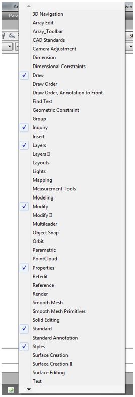
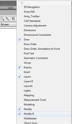
To enable or disable the display of a toolbar menu, place the Graphic cursor on any icon on a currently displayed toolbar and right-click the mouse. A list of all the available toolbar menus will display as shown in Figure 1-12. Click the name on the toolbar menu to toggle its display. A checkmark beside the toolbar’s name indicates that it is currently displayed in the Graphic window.
Dialogue Boxes and Windows
When a menu item has 3 dots after it as shown in Figure 1-13 it indicates that there is more. When clicked, it will open a dialogue box or a window.
Dialogue Boxes
AutoCAD uses many different dialogue boxes to speed the drawing process. A dialogue box is an effective and efficient method for AutoCAD to allow you to modify or enter information, settings, and sizes. While a dialogue box is open, no other work can be done in the current drawing. It must be closed before continuing to the next command. If you close a dialogue box by clicking the X in the top right corner, it will cancel your current input in the box. If you want to save your input, you must click the OK button. A typical dialogue box is shown in Figure 1-14.

Windows
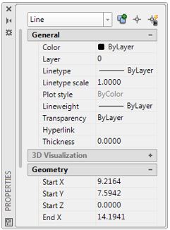
AutoCAD uses many different windows to speed the drawing process. Compared to a dialogue box, a window is a more efficient method for AutoCAD and you to communicate. Windows are interactive and display data and information about the current drawing or objects in that drawing as the drawing is being worked on. Unlike a dialogue box, a window updates automatically and can remain on the screen as you work on the drawing. You must close a window by clicking the X in the upper corner. This will not cancel you input. A typical window is shown in Figure 1-15.
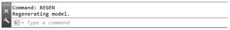
Command Line Window
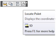
The Command Line window is used, by you, to enter keyboard commands and user inputs. It is also used by AutoCAD to output information to you. See Figure 1-16. It is one of the ways that you communicate with AutoCAD and is a very important way for AutoCAD to communicate with you. It is important for you to watch this window closely when you are drawing. It is used by AutoCAD to ask for information, instruct you to what data it requires, or display answers to your inquiries. This will be discussed in much greater detail in Module 2.
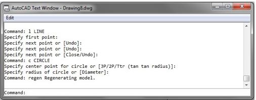
Text Window
The Text window, Figure 1-17, displays all of the commands that were entered by you and AutoCAD’s responses to those command for the duration that the current drawing is open. This is one way for you to look back at the commands, user input, and AutoCAD’s responses. To toggle the display of the Text window, press F2.
The Mouse
AutoCAD is programed to use the three buttons on a mouse as follows:
Left Button: This is the pick button. Use it to pick objects, pick menu items, or to select locations on the drawing.
Middle Button: The middle button, or wheel, is used to zoom and pan around the drawing. This will be discussed in detail in Module 9.
Right Button: The right button has two uses. If pressed and released quickly, it repeats the last command. If pressed and held in, it displays the cursor menu. See Figure 1-18.
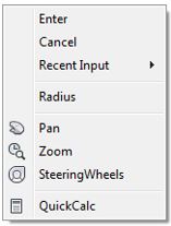
The cursor menu displays differently depending on the current or last command entered. It can be a very helpful menu once you become a more experienced user.
WORKALONG: Learning to Use AutoCAD’s Interface Using Toolbar Menus
If you are using Ribbon menus, skip forward to WORKALONG: Learning to Use AutoCAD’s Interface using Ribbon Menus.
Step 1
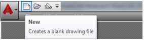
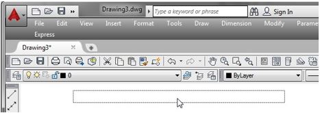
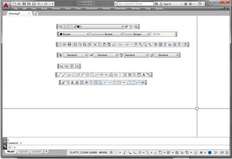
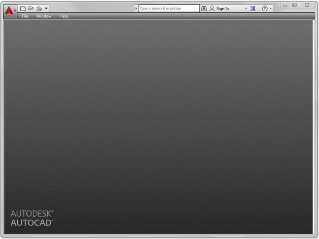
Launch AutoCAD. AutoCAD’s blank window will display. (Figure Step 1)

Step 2
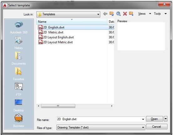
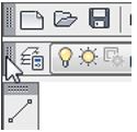
Click the New icon located in the upper right corner as shown in the figure. This will open the Select Template dialogue box. (Figure Step 2)
Step 3
In the Select Template dialogue box, click the template file: 2D English to highlight it. Then click the Open button. This will open AutoCAD’s Graphic window. (Figure Step 3)
Step 4
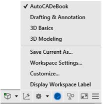
Click the small arrow in the Workplace Switching icon again on the Status bar. Click the workspace: AutoCADbook to set it as the current workspace. Make sure that the check mark is beside AutoCADbook as shown in the figure. Your Graphic window should match the figure. (Figure Step 4A and 4B)

Step 5
Check to ensure that the Model tab is enabled. It is located on the bottom left corner of the window. If it is not enabled, click it with the left mouse button. (Figure Step 5)

Step 6
Disable all features on the Status bar by clicking any that display with a blue background as shown in Figure Step 6A. All features should display with a gray background as shown in Figure Step 6B. (Figure Step 6A and 6B)


Step 7
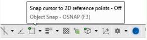
Click the coordinate display, located on the left side of the Status bar, to disable it shown in Figure Step 7A. Click it again to enable it as shown in Figure Step 7B. (Figure Step 7A and 7B)


Step 8
Click the Draw item in the Pull-down menu to pull down the menu. Hold the Graphic cursor over the flyout triangle at the end of the Circle command to force the flyout to display. (Figure Step 8)
Step 9
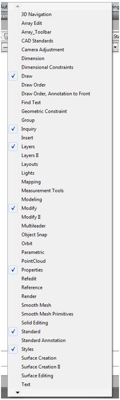
Move the Graphic cursor onto any toolbar icon and right click the mouse. This will pull down a list of all available toolbar menus. The ones that are preceded with a checkmark are enabled and are currently displayed in the Graphic window. Ensure that the toolbars Draw, Inquiry, Layers, Modify, Properties, Standard, and Styles are the only ones enabled. Click on the name to toggle the display of the toolbar. (Figure Step 9)
Step 10
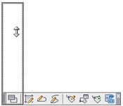
Move the Graphic cursor onto the lines at the end of the Layers toolbar. Press and hold the left mouse button down and drag the toolbar somewhere into the Graphic window and release the button. (Figure Step 10A, 10B, and 10C)
Step 11
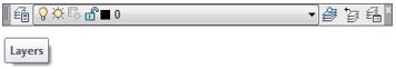
Move the cursor onto bars at the end of the Layers toolbar and hold it for a few seconds. The toolbar’s name, Layers, will display as a tooltip. (Figure Step 11)
Step 12
Using what was taught in Step 9, drag all six toolbars into the Graphic window as shown in the figure. (Figure Step 12A and 12B)
Step 13
Using what you learned doing Steps 9 and 12, drag all six toolbars back into position by docking them to the locations shown in the figure. (Figure Step 13)
Step 14
Using what you learned earlier in the workalong, enable the display of the Modify II toolbar. It will display as a floating toolbar. (Figure Step 14A and 14B)
Step 15
Move the Graphic cursor onto the top edge of the Modify II toolbar until the cursor displays as double arrows. See Figure Step 15A. Press the left mouse button and while holding it down, drag the toolbar upwards until it matches Figure Step 15C. (Figure Step 15 A, 15B, 15C)
Step 16
Using what was taught in Step 14 and 15, enable the display of the Object Snap toolbar and change its appearance to match the figure. (Figure Step 16)
Step 17
Close the Object Snap and Modify II toolbars by clicking the X in the top right corner of each toolbar.
Step 18
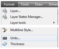
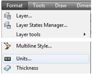
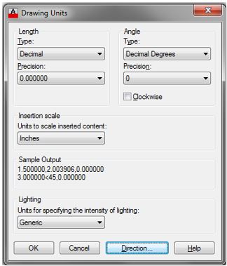
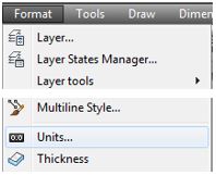
Click Format on the Pull-down menu and then click Units to open the Drawing Units dialogue box. Click OK to close the dialogue box. (Figure Step 18A and 18B)
Step 19
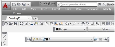
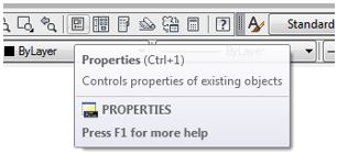
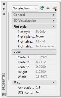
Move the Graphic cursor onto the icons in the Standard toolbar. As you move it over the icons, tooltips with the toolbar’s name will display. Find the Properties icon. Click it to open the Properties window. (Figure Step 19A and 19B)
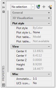
Step 20
Click the X in the top corner of the window to close it.
Step 21
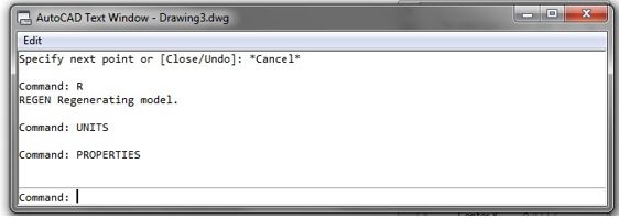
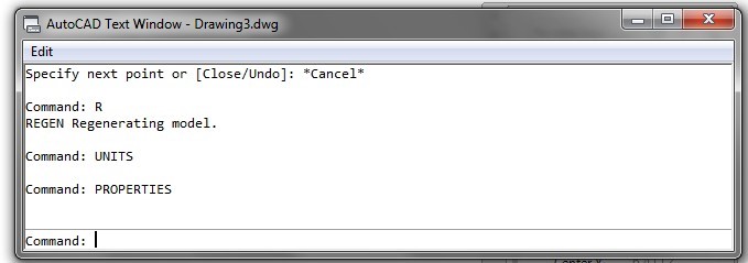
Press the function key F2. It will open the Text window as shown in the figure. (Figure Step 21)
Step 22
Press the function key F2 again to close the Text window.
Step 23
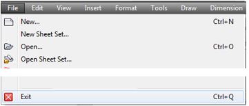
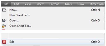
Click File on the Pull-down menu. Click Exit to close AutoCAD. If you are asked if you want to save the drawing, click No. (Figure Step 23)
Step 24
Go to Module 2.
WORKALONG: Learning to Use AutoCAD’s Interface using Ribbon Menus
If you are using Toolbar menus, go to Module 2.
Step 1
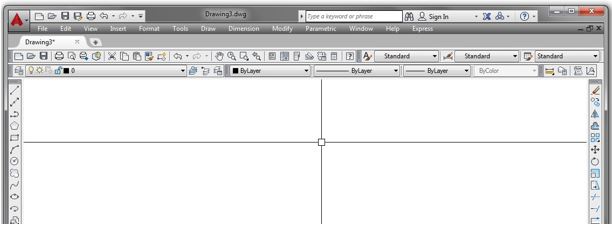
Launch AutoCAD. AutoCAD’s blank window will display. (Figure Step 1)
Step 2
Click the New icon located in the upper right corner as shown in the figure. This will open the Select Template dialogue box. (Figure Step 2)

Step 3
In the Select Template dialogue box, click the template file: 2D English to highlight it. Then click the Open button. This will open AutoCAD’s Graphic window. (Figure Step 3)

Step 4
Click the small arrow in the Workplace Switching icon again on the Status bar. Click the workspace:
Drafting & Annotation to set it as the current workspace. Make sure that the check mark is beside Drafting & Annotation as shown in the figure. Your Graphic window should closely match the figure. (Figure Step 4A and 4B)

Step 5
Check to ensure that the Model tab is enabled. It is located on the bottom left corner of the window. If it is not enabled, click it with the left mouse button. (Figure Step 5)

Step 6
Disable all features on the Status bar by clicking any that display with a blue background as shown in Figure Step 6A. All features should display with a gray background as shown in Figure Step 6B. (Figure Step 6A and 6B)


Step 7
Click the coordinate display, located on the left side of the Status bar, to disable it shown in Figure Step 7A. Click it again to enable it as shown in Figure Step 7B. (Figure Step 7A and 7B)
USER TIP: You can easily check to see if a feature on the Status bar is enabled or disabled by holding your graphic cursor on the icon. A pop up window will display indicating the name of the feature and whether it is currently on or off as shown in the figures.

Step 8
Click Format on the Pull-down menu and then click Units to open the Drawing Units dialogue box. Click OK to close the dialogue box. (Figure Step 8A and 8B)

Step 9
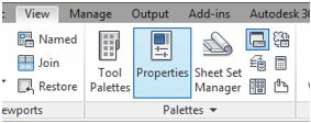
Click the View tab on the Ribbon menu. Find the Properties icon. Click it to open the Properties window. (Figure Step 9A and 9B)
Step 10
Click the X in the top corner of the window to close it.
Step 11
Press the function key F2. It will open the Text window as shown in the figure. (Figure Step 11)
Step 12
Press the function key F2 again to close the Text window.
Step 13
Click File on the Pull-down menu. Click Exit to close AutoCAD. If you are asked if you want to save the drawing, click No. (Figure Step 13)
Step 14
Go to Module 2.
Key Principles
Key Principles in Module 1
- The Graphic window is used most of the time when working in AutoCAD.
- The crosshairs indicates your current location. Think of it as the point of the pencil. It is used extensively while working in AutoCAD. It is one of the most important tools.
- The pickbox is a small square located at the intersection of the crosshairs.
- The Status bar is positioned across the bottom of the Graphic window and becomes a very important part of your day-to-day AutoCAD work.
- The Model and Layout tabs are used to enable the display of the model or a layout.
- The Command Line window is used to enter keyboard commands and user inputs. It is also used by AutoCAD to output information to you.
- The Pull-down menu Is located across the top of the Graphic window. If an item on the Pulldown menu has a small solid triangle at the end, it has a flyout menu associated with it.
- The toolbar menus are a series of icons that are located on a collection of menu bars.
- AutoCAD uses many different dialogue boxes to speed the drawing process. A dialogue box is an effective and efficient method for AutoCAD to allow you to modify or enter information, settings, and sizes.
- AutoCAD uses many different windows to speed the drawing process. Compared to a dialogue box, a window is a more efficient method for AutoCAD and you to communicate.
- AutoCAD is programed to use the three buttons on a mouse. The left button is the pick button.
- AutoCAD’s Text window displays all of the commands that were entered by you and AutoCAD’s responses to those command for the duration that the current drawing is open. To toggle the display of the Text window, press F2.
