
3 Microscope Lab
"The eye of a human being is a microscope, which makes the world seem bigger than it really is." -Khalil Gibran
Gillian Backus; Heidi W. Wangerin; and Paula Rodgers
Objectives
- Identify and define the parts of a microscope.
- Explain and apply the concept of depth of field.
- Describe and demonstrate proper handling and care of the microscope.
- Describe and demonstrate proper focusing techniques and light adjustments at all magnifications.
- Describe changes in the field of view when using the different objective lenses.
- Correctly store the microscope.
Terminology Checklist
Parts of the Microscope
|
Properties of the Microscope
|
Outline of Lab
- Activity 1: Parts of a Microscope
- Activity 2: Depth of Field
- Activity 3: Field Diameter and Review of Cells
Activity 1: Parts of a Microscope
Materials:
|
Background:
In lab today you will be reviewing how to use and care for the compound microscope. Compound microscopes have two sets of lenses, an ocular lens which is connected to the head of the microscope and magnifies objects 10 times its actual size, and a set of objective lenses which have varying magnifications (Figure 1). The magnification of an objective lens is indicated by a number (4x, 10x, 40x or 100x) written on the side of each lens. The objective lenses can be rotated to change the magnification using the revolving nosepiece (never grab the objective lenses). The ocular lens and the objective lenses, calculated together, provide the total magnification using the formula below:
Total Magnification = Ocular Lens x Objective Lens
For example, if the ocular lens magnifies 10x and if the scanning objective (4x, red) is in place, the total magnification would be 40x (10 x 4 = 40x). Always report the magnification as total magnification.
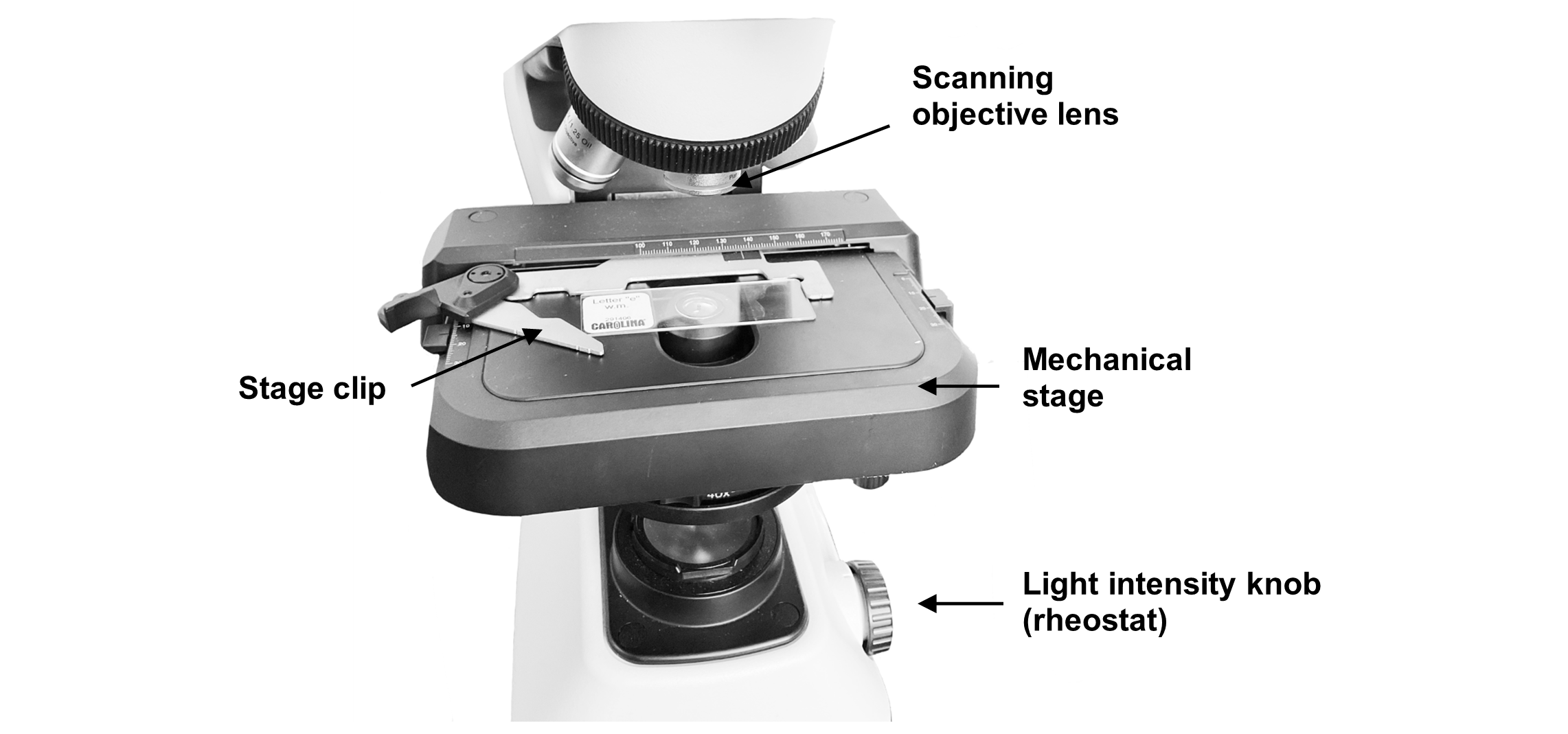
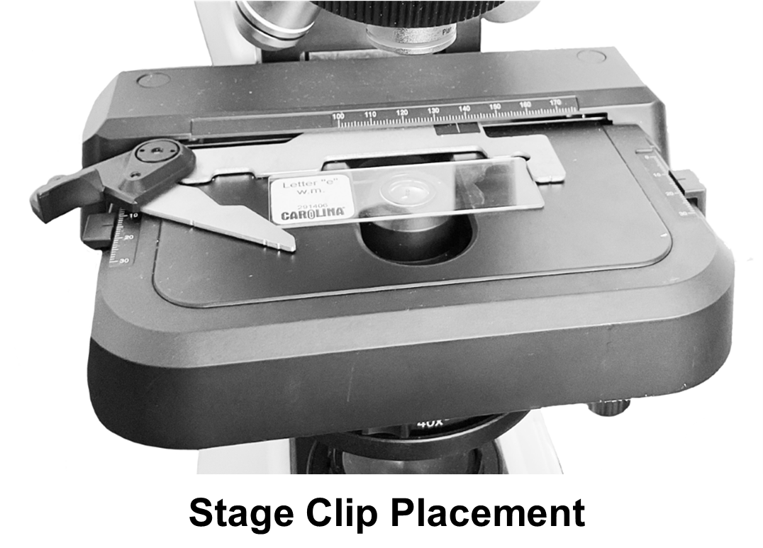
Light travels from the illuminator (light source) situated in the base of the microscope up through a condenser. The condenser helps to focus the light on the specimen as it sits on a microscope slide held in place on the mechanical stage by a stage clip (Figure 2). The condenser houses the iris diaphragm lever that controls the amount of light which travels up to the specimen, much like the iris of your eye controls the amount of light that enters your eye (Figure 1).
After the light passes through the specimen, it travels into the objective lens, up through the ocular lens and reaches your eye above. There are two small stage adjustment knobs attached to the stage of the microscope. One allows you to move the specimen left and right and the other toward you and away from you. Along the base of the microscope, you will see two round knobs called the coarse adjustment knob and the fine adjustment knob (Figure 1). Both adjust the up and down position of the stage to focus the image.
Figure 1: Left and right lateral views of the compound microscope.
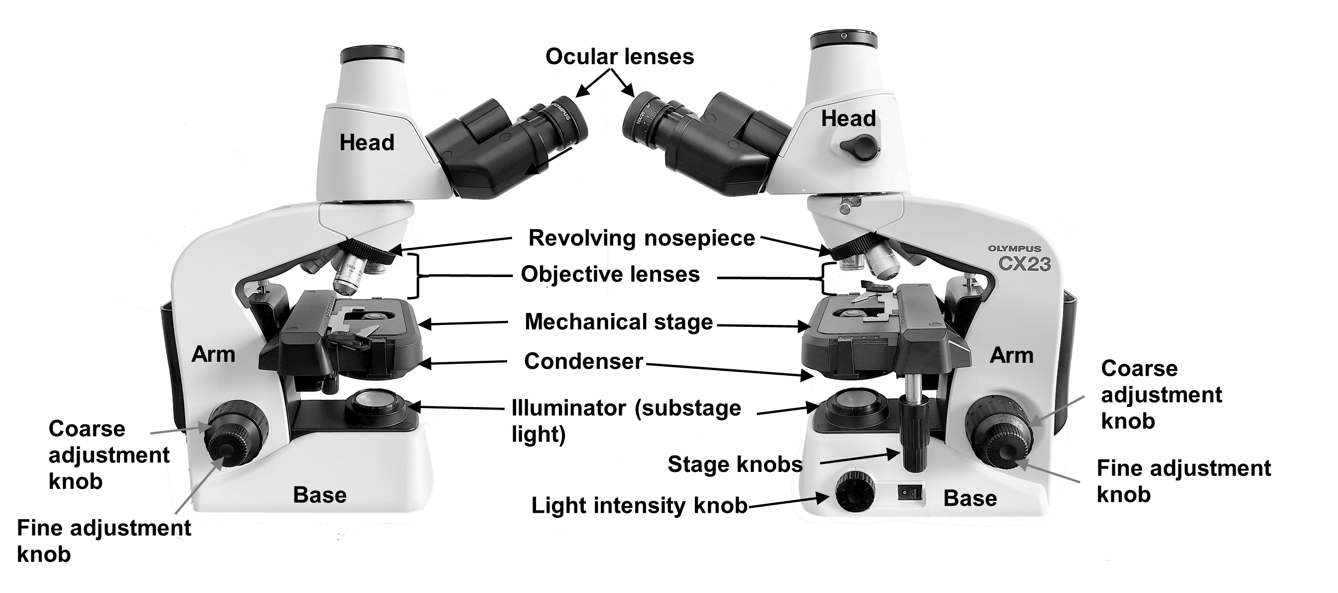
Figure 2: Image of the microscope with the correct placement of a slide on the stage.
Procedure:
1. Calculate the total magnification of each lens and write it in the table below:
| Objective Lens | Total Magnification |
| Scanning objective (4x, red) lens | |
| Low–power objective (10x, yellow) lens | |
| High–power objective (40x, blue) lens |
2. Locate a microscope.
3. Carefully remove the microscope and place it on the lab bench using two hands – one on each handle on the arm.
4. Using the images in the lab manual and laminated terminology labels (with sticky tack), label the parts of the microscope. Do not place any sticky tack directly on the lenses of the microscope!
5. Once you have attached the laminated terminology labels to the microscope using sticky tack, have your instructor sign below.
Instructor’s Initials for labeled microscope: _______________
6. Remove the labels and return them to the binder.
Activity 2: Depth of Field
Materials:
|
Background:
In this activity you will learn how to clearly view the different layers of a thick specimen under the microscope. You will also learn about working distance, changes in resolution, and depth of field for each of the three objective lenses.
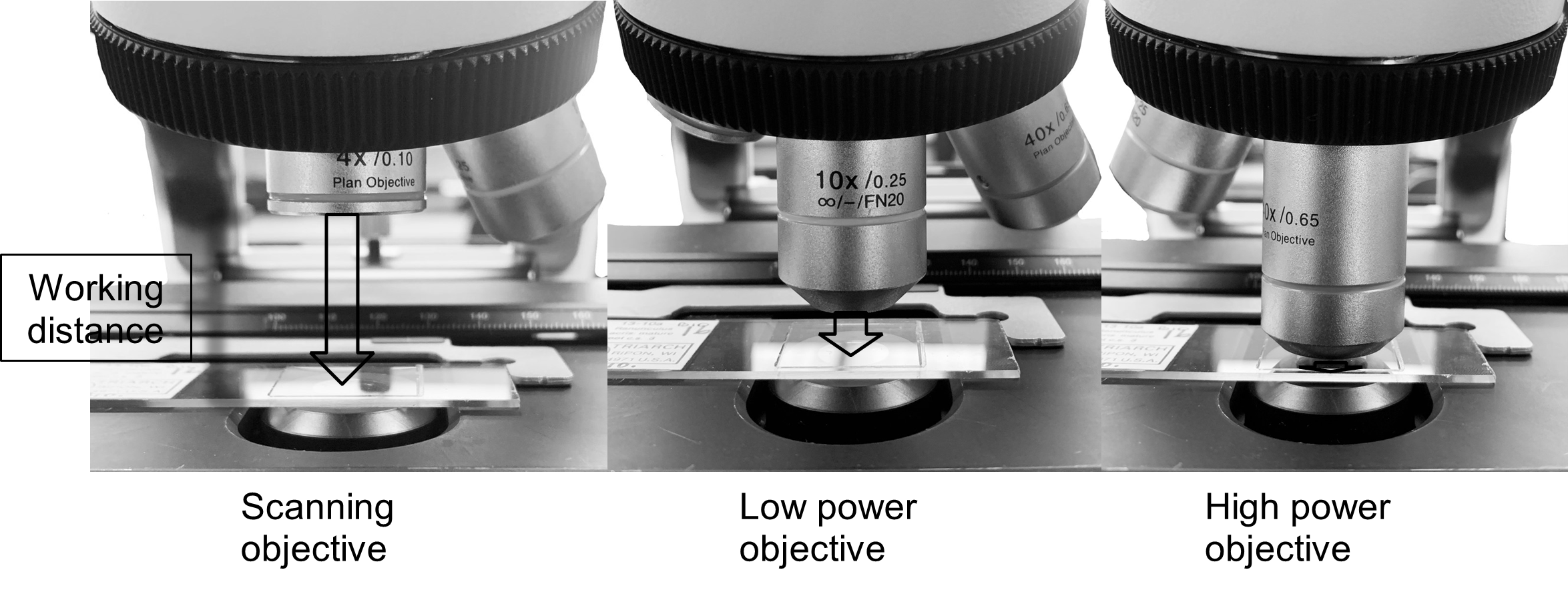
Working distance is a measure of the distance between the bottom of the objective lens, and the slide once the image on the slide is in focus. (Figure 3) As you increase magnification, working distance decreases. You must be perfectly focused before moving to the next objective lenses; otherwise, you risk damaging the high-power objective (40x, blue).
Figure 3: Working distance is a measure of the distance between the bottom of the objective lens.
Resolution is the ability to observe two distinct points separately. As magnification increases, resolution increases, to a point. If you continue to increase the magnification beyond the resolution limits of the microscope, it can lead to empty magnification in which resolution of the image is poor. The image will appear fuzzy and you will not be able to focus.
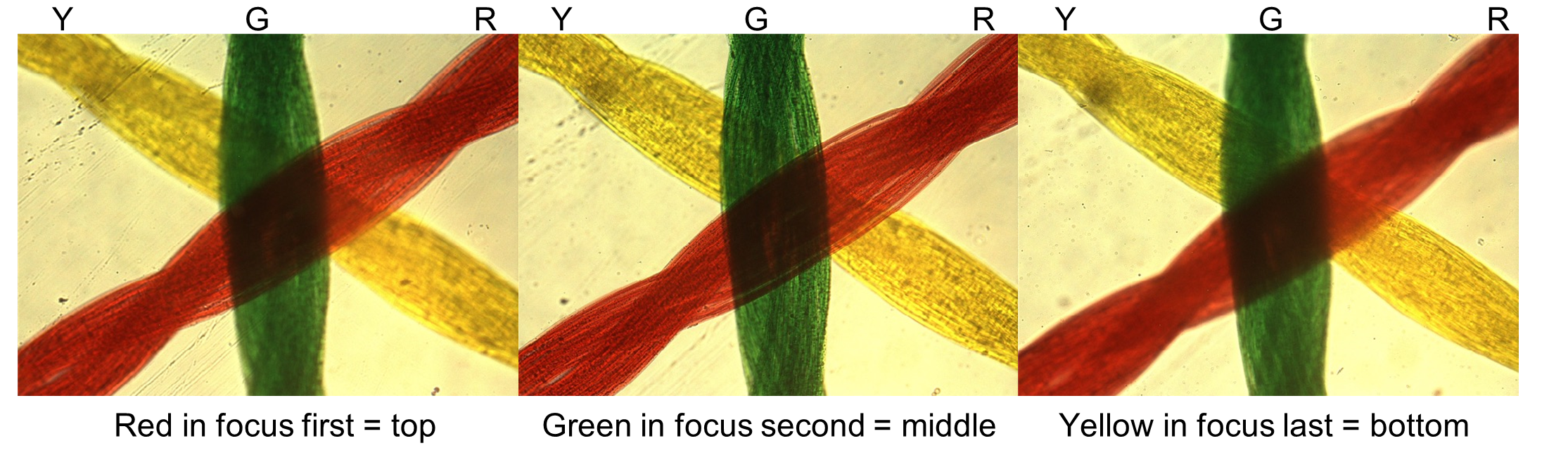
Figure 4: Depth of field is a measure of the thickness of a specimen that you see in focus at one time. At low power magnification only parts of the mite can be in focus.
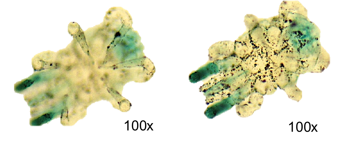
Depth of field is a measure of the thickness of a specimen that you see in focus at one time. (Figure 4) You will be using the color thread slide to investigate this property of the microscope. This slide has three different colors of thread laid across each other. As you attempt to focus with the low or high-power lens, notice that you cannot get all three threads in focus at the same time.
To determine the relative position of all three colored threads, use your fine adjustment knob to gradually raise and lower your objective lens slowly (known as “focusing up and down”) and observe the order in which the threads go in and out of focus (Figure 5). As your objective lens approaches the slide, the first thread to come into focus is on the top. Remember you should always start with the stage in the lowest position, and as you raise the stage the top thread is the first one to come into view, middle second, and bottom thread last. As magnification increases, therefore, the depth of field will decrease. The image above shows that the red threads came into focus first, then the green threads and last the yellow threads. This would mean that the red is on top, green is in the middle, and yellow is on the bottom.
Figure 5: String slide at three different focal depths.
Procedure:
1. Before putting a microscope slide on the microscope, first use the revolving nosepiece to put the scanning objective (4x, red) in place, then rotate the revolving nose piece and move the low-power objective (10x, yellow), and then the high-power objective (40x, blue) in place.
2. How did the working distance change as you increased magnification?
3. Always clean your microscope and slide before you begin. Put a drop of isopropyl alcohol on a clean piece of lens paper (Never use any other paper product on the lens!) and gently clean the ocular lens, each objective lens, and the slide
4. Plug in your microscope and turn it on.
5. Make sure the scanning objective (4x, red) is in position.
6. If the stage is not already lowered, use the coarse adjustment knob to lower the stage until it stops.
7. Place the “string” slide on the stage and use the stage clips to hold the slide in position. The stage clips “hug” the slide in place. Do not place the slide under the clips.
8. While watching the specimen from the side of the microscope, use the stage adjustment knobs to move the slide around until the light is shining through the specimen.
9. Now, look into the ocular eye pieces. Using the coarse adjustment knob, raise the stage until the specimen comes into focus. Once the specimen is mostly in focus, use the fine adjustment knob to bring it into sharp focus.
10. Put the strings in focus first under scanning objective (4x, red), then on low-power objective (10x, yellow). Make sure you are centered on the three strings before moving to the high-power objective (40x, blue).
11. Which lens has the best resolution (allows you to see the most detail of the strings)?
12. Slowly observe the slide as you focus up and down to determine the relative position of each thread (please note every slide has a different position of the string colors). Determine the relative position of the 3 colored threads on your slide.
Slide Letter: ______________
Top thread color: ______________
Middle thread color: ______________
Bottom thread color: ______________
13. Before you put away this slide, have your instructor check your work and sign below. Do not put away your slide until after your instructor checks your work.
Instructor’s initials for thread slide: ________________
Activity 3: Field Diameter and Review of Cells
Materials:
|
Background:
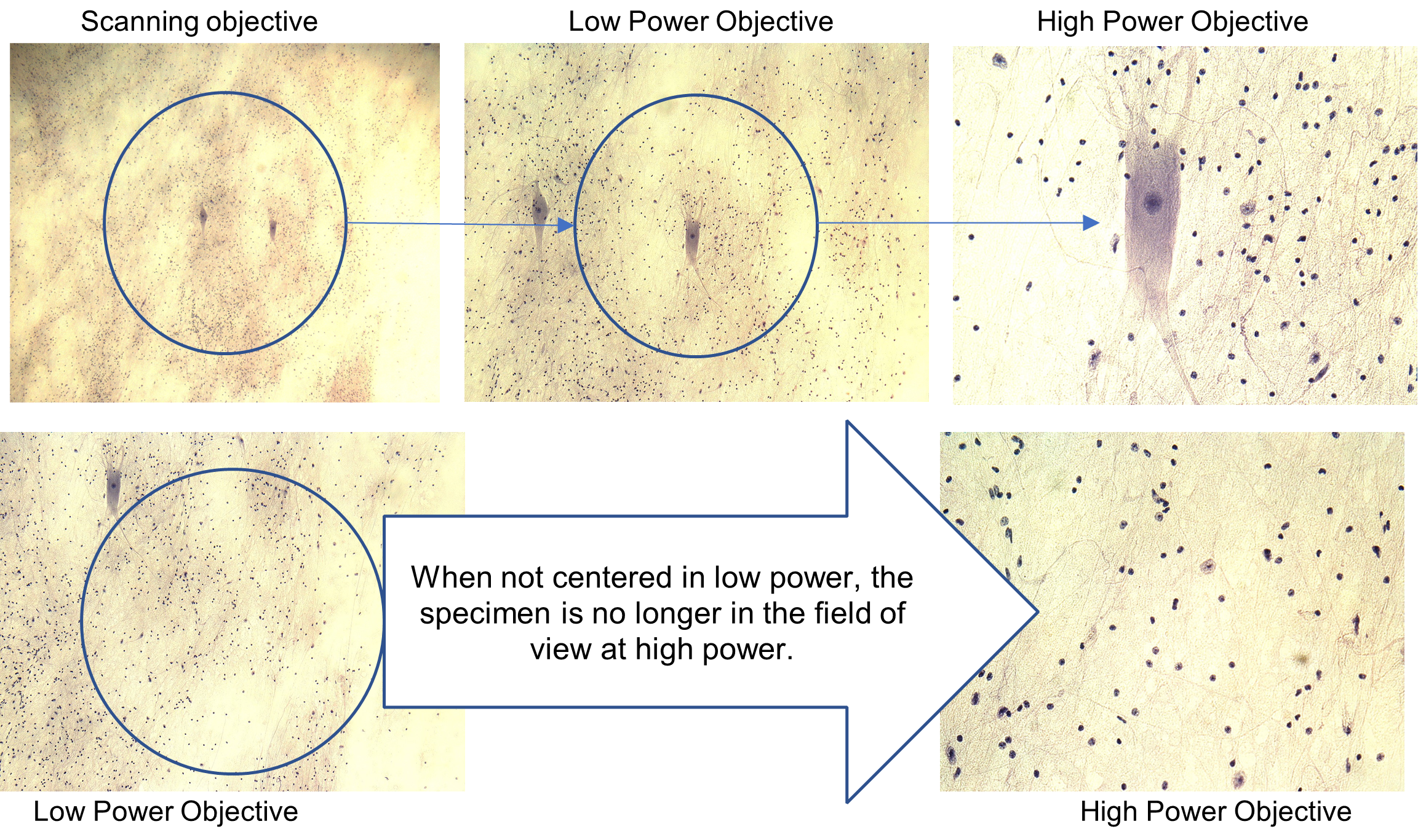
Another important property for each lens is the field of view or field diameter. This is the diameter of the circle of light that you see through the microscope. As you move to higher magnification, the diameter of the field decreases. It is always important to center the part your specimen you are focusing on before moving up in magnification, otherwise it might not be in your new field of view.
Figure 6: Example of the field of diameter and the importance of centering a specimen.
In this lab you will view slides of cells with different color stains and at different magnifications, including your own cheek cells! You will need to adjust the contrast, degree of difference between the lightest and darkest parts of a specimen, with each slide and objective lens. To enhance the (contrast), the light intensity can be changed by:
-
- adjusting the diaphragm lever
- raising or lower the substage condenser using the substage condenser adjustment knob
- turning the light intensity knob (Rheostat dial) to a higher or lower setting
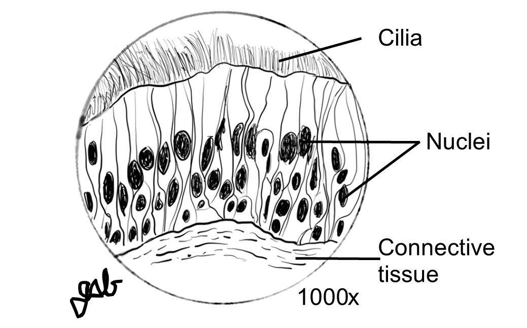
Finally, you will learn to make a proper scientific drawing of a microscope slide. This is an important skill in biology. All drawings must be:
-
- in pencil
- neat
- labeled correctly using straight non-crossing lines
- total magnification written below the image
Figure 7: Proper scientific drawing of a microscope slide.
Procedure:
1. View the slide of two different types of cells, nerve cells and skeletal muscle cells (Motor End Plate) below. Skeletal muscle cells are long parallel cells (fibers) that appear striped (striated). They are much thicker than the nerve cells which are long and thin like a wire. Identify the nerve cell and muscle cell on the low-power image below:
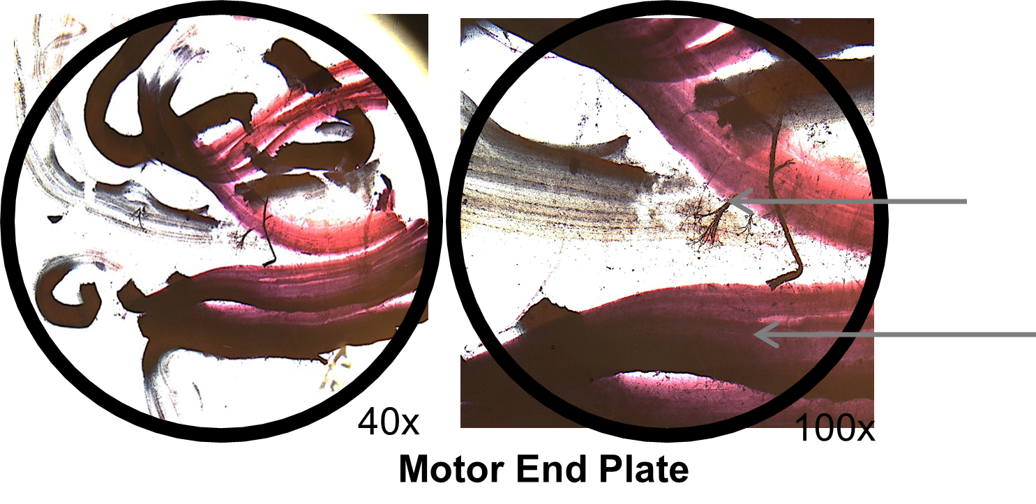
2. Compare the images above of the motor end plate under the scanning and low power lens. How does the field diameter change as you increase magnification from scanning to low power?
3. Make sure the scanning objective (4x, red) is in position. If not, use the revolving nose piece to click the proper lens into place.
4. If the stage is not already lowered, use the coarse adjustment knob to lower the stage until it stops.
5. Place the “peripheral nerve” slide on the stage and use the stage clips to hold the slide in position.
6. While watching the specimen from the side of the microscope, use the stage adjustment knobs to move the slide around until the light is shining through the specimen.
7. Now, look into the ocular eye piece. Using the coarse adjustment knob, raise the stage until the specimen comes into focus. Once the specimen is mostly in focus, use the fine adjustment knob to bring it into sharp focus. It should appear similar to the image on the right.
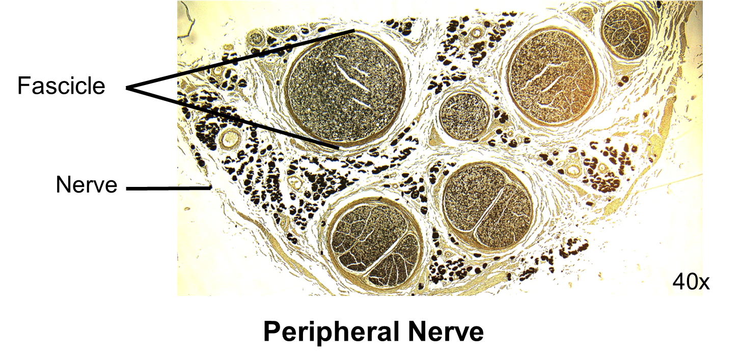
8. Place one of the fascicles, a bundle of nerve cells cut in cross section, in center and in focus on the microscope slide.
9. Turn your objective to the low power objective (10x, yellow) without moving the slide or stage. At low-power objective (10x, yellow) use only the fine focus knob to bring the specimen into sharp focus.
10. Again, center the specimen.
11. Turn your objective to the high-power objective (40x, blue) without moving the slide or stage. At high-power objective (40x, blue) use only the fine focus knob to bring the specimen into sharp focus.
12. Again, center the specimen.
13. In the space below, make a scientific drawing at high power. Locate and label a single cell which will appear as a small circle within the fascicle.
 14. We will now view a living cell, your own cheek cells! Please wear gloves.
15. Get a clean, dry microscope slide and coverslip.
16. Place a drop of methylene blue dye in the middle of the slide.
17. Using a toothpick, gently scrape the inside of your cheek.
18. Dip and swirl the toothpick in the dye that you placed on the microscope slide.
19. Place a coverslip on the slide by angling it at a 45-degree angle and slowly lowering it on top of the solution on the slide. This will minimize air bubbles on the slide.

20. Place the slide on the microscope and locate the cells at scanning. Note: the cells will be small and lightly stained. You will likely need to adjust the iris diaphragm to decrease the light intensity.
21. Once you have found a cluster of cells, use proper microscope technique to view them at low-power, and then at high-power.
22. Draw an image of a cheek cell at high power. Label the nucleus which will appear as a slightly darker staining circle approximately in the middle of the cells. Also label the plasma membrane (outer barrier), nuclear membrane (cell membrane around the nucleus) and the cytoplasm, the area inside the plasma membrane.
23. You are now ready to put the microscope away. Please complete each step below.
24. Turn off the power to the microscope, unplug it, and remove the power cord and adaptor.
25. Lower the microscope stage to its lowest position.
26. Move the stage all the way to the right so that the mechanical stage arms are aligned with the rest of the microscope.
27. Remove any slide on the stage and rotate the nosepiece to the scanning objective (4x, red).
28. Use lens paper and isopropyl alcohol to carefully clean the objectives and the ocular lenses.
29. Return the microscope to its proper storage location, making sure to carry the microscope properly with both hands – one hand on each handle on the side of the arm of the microscope.
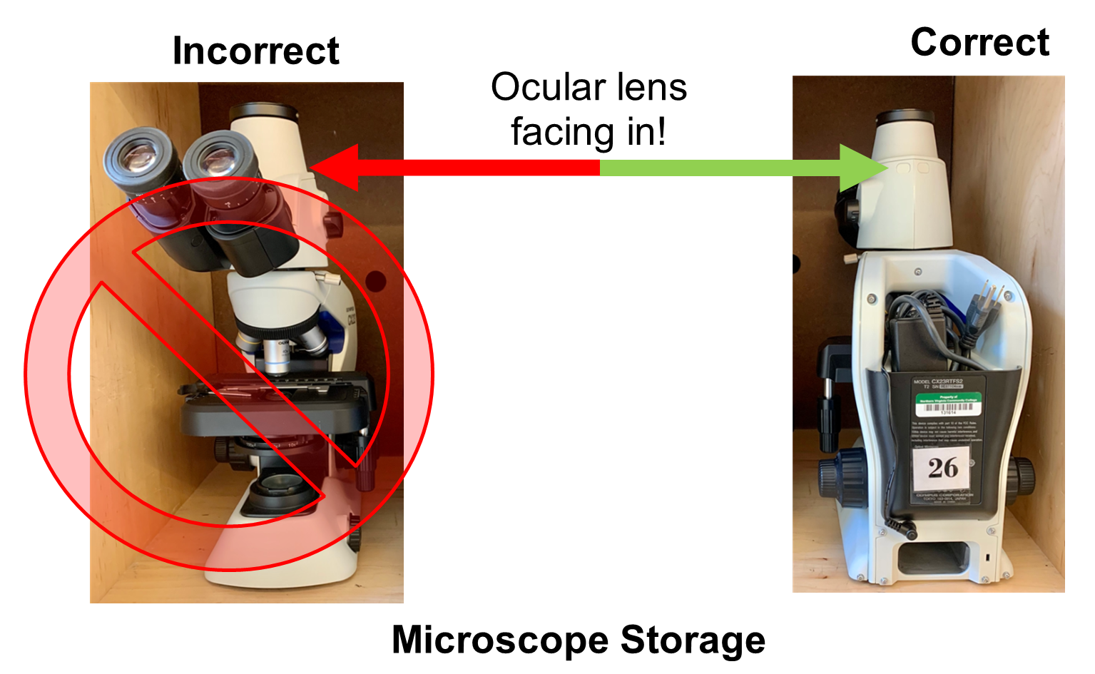
30. Place the microscope in the cabinet with the arm and oculars facing out.
31. Spray tables with disinfectant and wipe down tables.
32. Return all materials to the side bench.
33. Once you have cleaned up, call your instructor to have them sign the exit ticket at the start of the post-lab.
Creative Commons Citations:
- Case-Study Based OER Lab Manual for A&P I © 2022 by G. Backus, H. Wangerin, P. Rodgers is licensed under CC BY-NC-SA 4.0.
- Figures 1, 2, 3, 4, 5 and 6 © 2022 by H. Wangerin, is licensed under CC BY-NC-SA 4.0.
- Figure 7 © 2022 by G. Backus, is licensed under CC BY-NC-SA 4.0.
- Stage Clip Placement, Motor End Plate, Peripheral Nerve, Wet Mount, Microscope Storage, Volvox Slide © 2022 by H. Wangerin, is licensed under CC BY-NC-SA 4.0.
